Visual Inspection of Laser Beam Melting Processes
Laser Beam Melting (LBM) systems create solid bodies layer-wise from metal powder (“3D printing”). The original 3D CAD drawing of the part is sliced into layers which define the part geometry in two dimensions. The build process is iterative: first, a thin layer of metal powder, 20 μm to 100 μm in height, is deposited on the build platform. Next, a laser follows the part geometry in the current slice and melts powder into solid material. The build platform is lowered and all steps are repeated to produce the part (Fig. 1). Laser Beam Melting is also known as (vendor-specific): Laser Forming, Selective Laser Melting (SLM), Laser-Cusing, Electron Beam Melting (EBM) and Direct Metal Laser Sintering (DMLS) (c. f. VDI standard 3404).
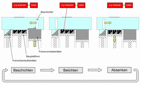
LBM systems are suitable for prototyping and small volume production and are utilized in a variety of fields, such as automotive or tooling. Today, despite its advantageous properties, LBM systems are rarely used in areas with high security requirements (aerospace, medical applications) due to the lack of quality control for parts built with LBM. Nondestructive testing is limited to external measurements and computer tomography, which is expensive, time consuming, and unable to examine parts thicker than 20 mm.
To enable widespread application of Laser Beam Melting processes in high security areas like aerospace or medical technologies, extensive quality control and process documentation is necessary.
Overview of Research Topics
- Layer image acquisition of powder bed and exposure result
- Build job documentation
- Process errors and error categorization
- Detection and analysis of elevated regions in powder bed images
Partners
Prof. Gerd Witt and Dipl.-Ing. Stefan Kleszczynski
Institute of Product Engineering at University of Duisburg-Essen
Contact
Joschka zur Jacobsmühlen, Tel.: +49 (241) 80-27974
Funding
Federal Ministry for Economic Affairs and Energy (BMWi) via the German Federation of Industrial Research Associations (AiF), IGF 17042 N, 2011-2013
Publications
See also research topics for an overview of selected publications.
Slides for Conference Publications
Research Topics
Image Acquisition of Powder Bed and Exposure Results
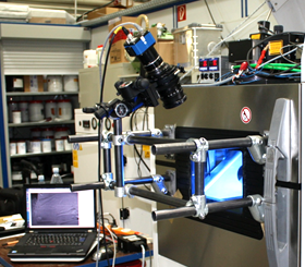
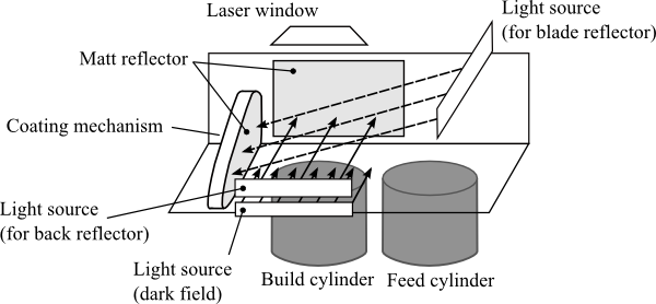
The requirements for the imaging systems are very demanding: it has to acquire images of structures of 50 – 100 µm size from great distance, as the camera cannot be placed inside the build chamber due to process atmosphere and laser radiation. The required resolution at microscopic level is achieved using a 29 megapixel industrial CCD camera (SVS29050 by SVS-VISTEK GmbH, Germany).
Build Job Documentation
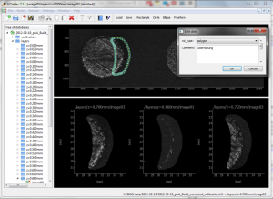
We have developed a data format for build job documentation based on the open Hierarchical Data Format (HDF5). It enables storage of layer images with associated metadata (imaging setup, machine state, image type), process parameters and reference part geometries (from CAD model). The HDF5 format is a self-describing container format, which does not impose any limits on the number or size of data objects. It is supported by many scientific applications (e.g. MATLAB) and programming languages (Python, C++,
Java).
The external camera position enables retrofitting of existing LBM systems and/or flexible positioning but causes perspective distortions which have to be corrected before analyzing layer images. We compute a homography from four circular markers which are “drawn” into the powder bed by the machine’s laser and detected in the acquired images. To deal with different image quality, we have developed a robust method for the automatic detection of calibration markers in powder bed images. The homography estimation minimizes the shape error between transformed reference marker shapes and detected elliptical markers yielding an image with corect aspect ratio and minimal distortions.
Process Errors and Error Categorization
Layer images enable the detection of common process errors, we have analyzed different error types and categorized them based on effect (reduced process stability or part quality), type and cause.
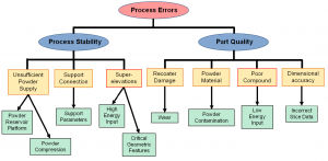
and cause. Click to enlarge.
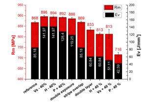
The effect of provoked process errors on mechanical part properties and associated layer appearance was examined to find a link between in-process layer images and post-process part performance.
During batch production of multiple identical parts in a single build job, we observed parts with deviating surface roughness in certain areas, which all faced away from the laser. This suggests a dependency of surface roughness on the part position in the build chamber. In this work we systematically reproduce and analyze this effect.
Detection and Analysis of Elevated Regions in Powder Bed Images
Elevated regions pose a major risk to process stability as collisions between recoater mechanism and elevated part regions may cause damage to the part and/or the recoater blade. Jammings of the recoater mechanism may cause process breakdowns.
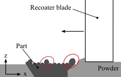
Layer images of the powder bed enable detection of elevated regions before they become dangerous. We have developed an image-based detection method for elevated regions, which segments regions inside the powder bed image, which are not covered by metal powder.
Analysis of detection results and correlation between accelerometer measurements and image-based measurements was examined in
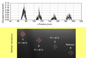
Quick evaluation of an entire build job and comparison of single parts (with and without support structures) is enabled by quantitative visualization of elevation analysis results. Ranking of parts by relative elevated area over all layers enables quick identification of stable process parameter settings, e.g. in the design phase of a new production process. You can view the slides of the conference presentation or refer to the following paper:
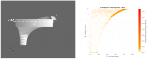
with decreasing overhang angle for increasing z. Right: x/z plot of elevated area the
starting z position and thereby the overhang angle of increasing elevations can be identified by
analyzing the right part boundary. Click to enlarge.
Detection of elevated regions is also feasible by using image descriptors computed on the melt result image. In contrast to aforementioned methods, the powder bed image is not used, here. We have evaluated different gradient-based descriptors which detect changes in the orientation of laser scan lines and trained classifiers to label image regions as “normal” or “elevated”.


